
3D Printing


3D Printing

In this blog, I will be documenting how I designed and printed my 3D object, which is the hinged box. The hinged part of the box cannot be made subtractively because the pin that is part of the top box is between the hinge of the bottom box. This is very difficult to make subtractively because the gap between the pin and the hinge is very small. Moreover, the pin is covered by the hinge and there must be a gap in between the pin and the hinge, so it is very difficult to be made subtractively. Therefore, it can be 3D printed for this assignment. 

I will be documenting the steps to design the hinged box here:
1. The first step to design the hinged box is to enter the parameters in Fusion360.


2. Create new component under assemble.


3. Next, create sketch and create a rectangle with length as BoxLength and the width as BoxWdith.

4. Extrude the sketch with the distance as BoxHeight.

5. Make the cube hollow by going to modify and click shell. Click on all 6 faces on the cube and set the inside thickness as "WallThickness".


6. Next, under construct, click on midplane, then click on the top and bottom face of the cube.


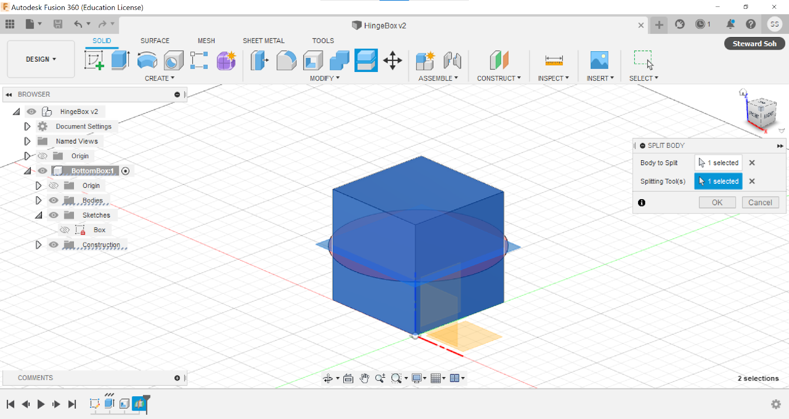
7. Go to split body, and select the cube for the body to spilt. Select the midplane construction plane as the splitting tool.


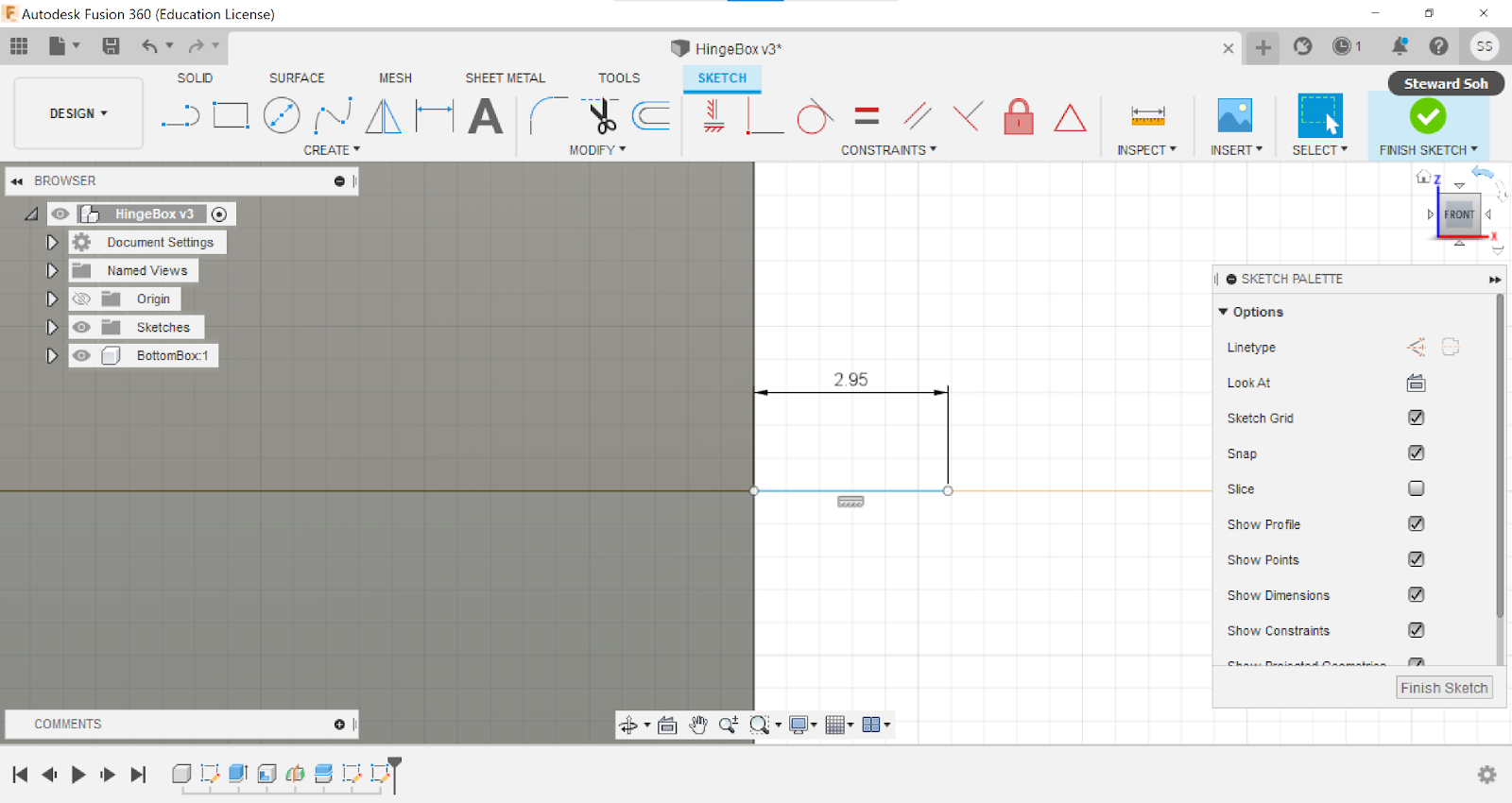
8. Next, click on one face of the bottom body, and create sketch.


9. Draw a 2.95mm line in the middle of the box


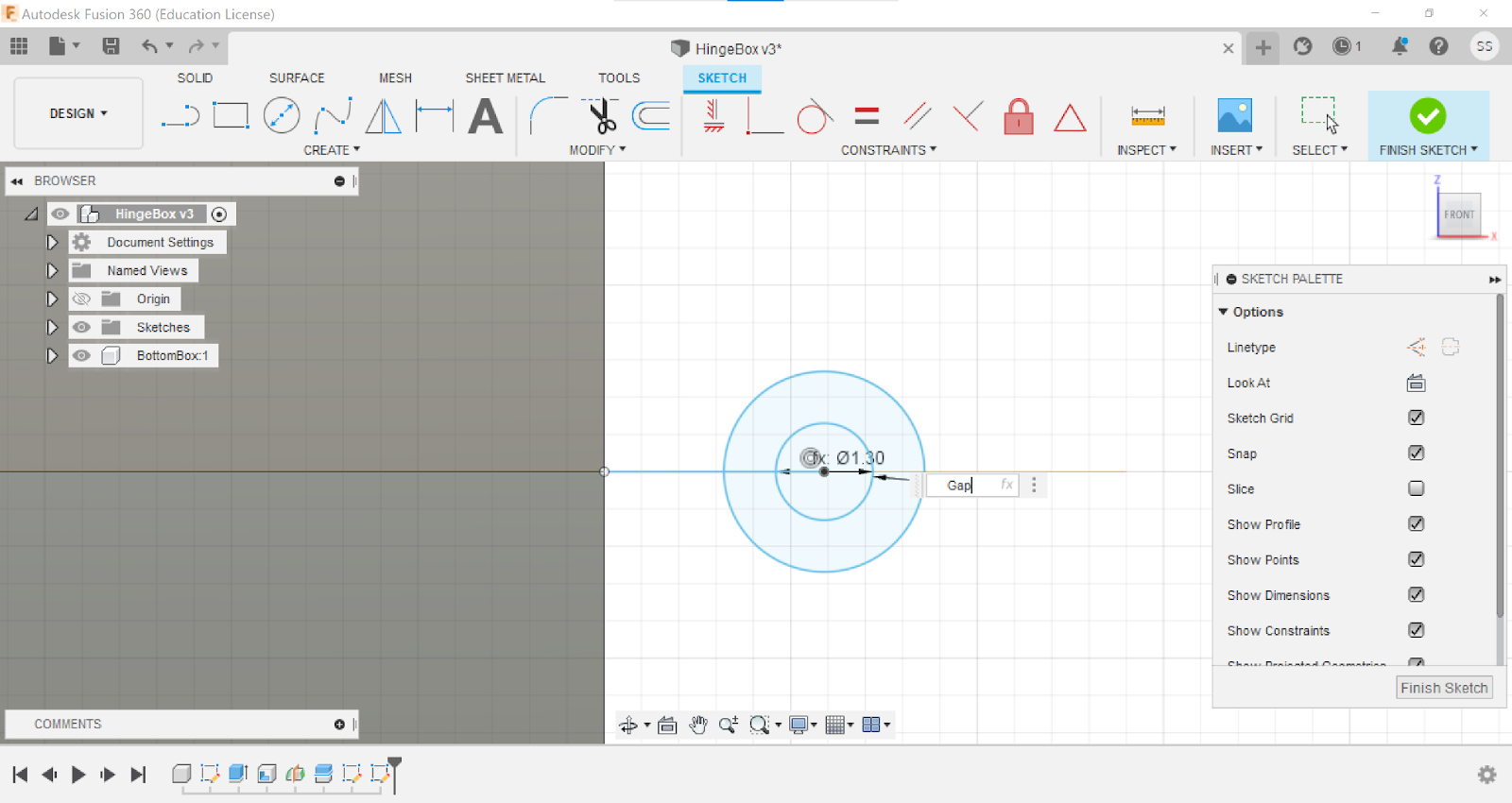
10. Click on center diameter circle, and create inner circle with diameter set as WallThickness at the end of the line.


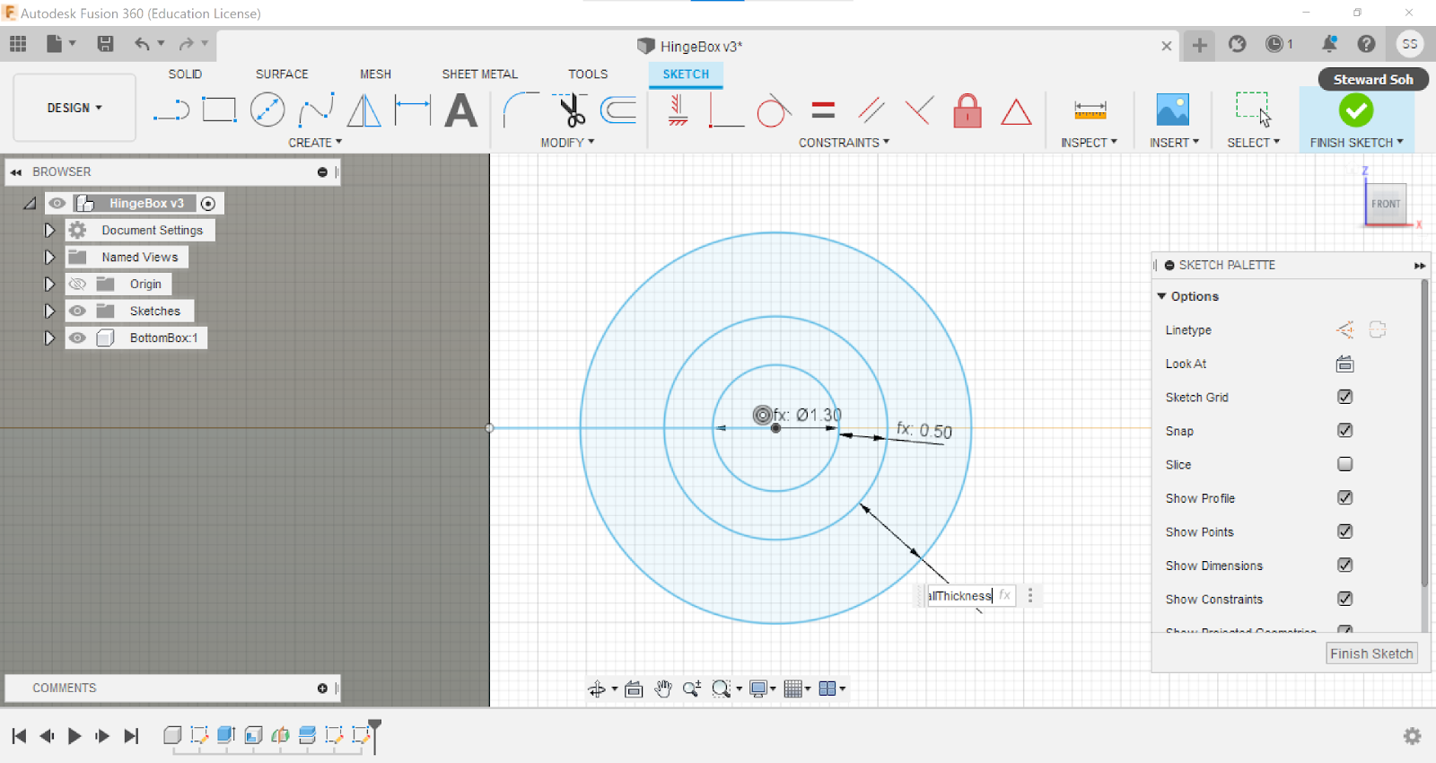
11. Create a bigger circle with a distance between the inner circle and outer circle as Gap.


12. Do the same for the third outermost circle.


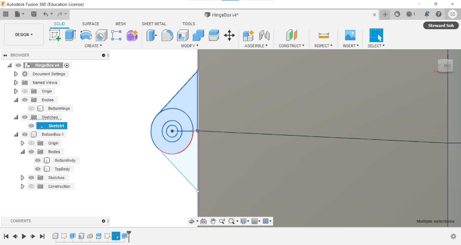
13. Draw a line from any point at the bottom box to the point at which the line is tangent to the outermost circle.


14. Click on dimension and select the box and the line and choose 45deg. Hold shift key and select the bottom hinge and the outer most circle, then right click and click on press pull.


15. Follow the settings on the right side of the screen. Set the extend type as To Object, and for the object, click on the bottom other side of the bottom box.


16. Next, hide the bottom hinge and unhide the sketch.


17. Select the top hinge and all the circles, right click and click on press pull. 


18. Then, follow the settings on the right side of the screen.


19. Select the innermost circle and extrude it. 


20. Create sketch on the top corner of the bottom box


21. Create a rectangle from the corner of the box with length as 5.5mm and width as WallThickness.


22. Create another rectangle right beside the rectangle created in step 21 with length as 5.5mm and width as Gap.


23. Draw a line using construction at the middle of the box.


24. Create another rectangle 11.5mm from the construction line with the length as 5.5mm and width as Gap.


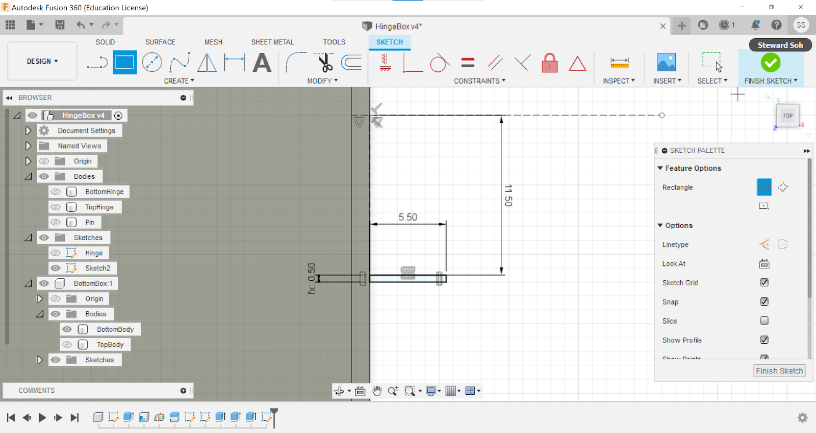
25. Click on mirror and select all the sketches that has been created from steps 20 to 24 for objects. The mirror line is the construction line at the middle of the box.


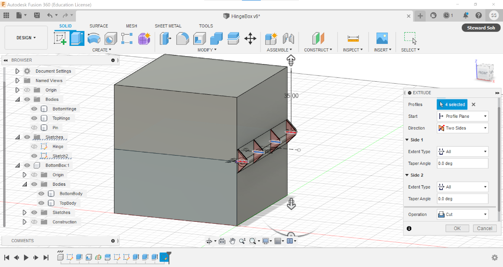
26. Select all the rectangles with the width set as Gap and click on extrude


27. For direction use two sides, both extend types set as all, and operation is set as cut.


28. Select these hinges, right click and remove these hinges. By selecting remove, it will remove the hinges but is still in the timeline. Each part of the hinge has space to revolve around center pin.


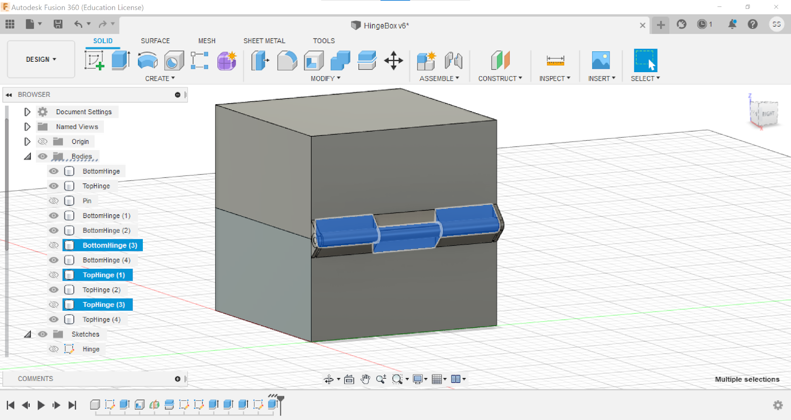
29. Rename top body to TopBox and drag it to the top of the browser tree


30. Select these parts of the hinge and drag it to TopBox.


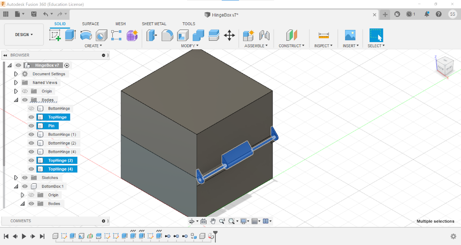
31. The browser tree should look something like that.


32. Next, go to assemble and click on as built joint, select both components. Select revolute for joint type, and select the centre of the pin. Double click the revolute arrow and key in -180 degrees for the best print quality and most efficient way to print.


33. Rotate the box back to the previous position and remove these bottom hinges, Then rotate the box back.


34. We were given maximum 1h to print our objects, so I had to readjust the parameters so that it will not take too long.


35. On Fusion360, save the object by clicking on save as mesh and import it to Cura. Set the size as 70% so the estimated time is about 1h 8min. 

Click on save to disk to save into the SD card for 3D printing.

Here's the embed file of the object:

Here's the link to download the stl file:

Here are some photos of the end product:

Reflection

In this session, the assignment was to design and document a 3D printed object that is non-subtractable. I have chosen to make a hinged box because the hinged area is non-subtractable, so it fits the requirement. I have searched through YouTube tutorials to look for a hinged box tutorial. I came across this video that was very informative and he also explained each step clearly and is very detailed. Through watching the videos and learning how to make the hinged box, I have learnt a few functions of Fusion360 that I have never seen before. For example, the as built joint and revolute functions are new to me. This function can be very useful when designing other objects that involves rotating parts. 

I feel that this assignment is important because it exposes me to many different functions on Fusion360, so I can improve on it. Moreover, this will also equip me with the skill to 3D print objects for our chemical product prototype and also for other projects. I find that this is quite interesting because I can use this skill to create more designs and print them at the 3D printers in school. I believe that this assignment will be very useful in this module because we will need to create a prototype for our chemical product. My group could make use of Fusion360 and the 3D printer to design and print the parts for the prototype. 

I used to think that Fusion360 is very difficult because I do not know how to use yet. Now that I have some knowledge of Fusion360, I find it easier to design things on this software. I look forward to learning more functions on Fusion360, so that I am competent enough to design other things for other purposes. So, when I have the time, I will look for Fusion360 tutorials and learn more about what it can do.

In conclusion, this has been a great experience because I get to learn new things that we never taught in school. It could help a lot in future for building prototypes. Therefore, I feel that this has been very fruitful and enriching for me.


References
  Kennedy, K., 2021. [online] Youtube.com. Available at: <https://www.youtube.com/watch?v=okgvaI06ntU> [Accessed 23 December 2021].
  Kennedy, K., 2021. [online] Youtube.com. Available at: <https://www.youtube.com/watch?v=iSBsBTMsGTk&list=PLrZ2zKOtC_-DR2ZkMaK3YthYLErPxCnT-&index=21> [Accessed 23 December 2021].

Comments

Popular posts from this blog

Home

Hi, Welcome to My Blog!! In this semester, I am taking a module called Chemical Product Design and Development. I will be documenting about everything I learn on this blog.  I am thrilled to start this module because I get to learn new skills such as laser cutting and Arduino Programming that will help refine my team's product idea. I am from Team Trio, and our team's product idea is an air-to-water machine which will absorb water vapour in the air and produce clean drinkable water.  My Personal Goals I want to improve my CAD skills on Fusion360. This is because I believe that 3D printing will be very important and relevant in future. Therefore, by mastering my CAD skills, I will be able to create many different product ideas with ease.  Another one of my personal goals is to master experimental designs. I believe that it will be very important that we know how to create experiments that will help us determine the objective accurately. This can help us a lot in our Final Year P